Alternator Circuit Explained - Alternator Upgrade Article back from 2001 - PA Performance.com : They can produce more current.. A car uses quite a lot of electricity to work the ignition and other electrical equipment. The following information is presented as a guide when wiring and troubleshooting alternators. The excitation system is responsible for supplying the field current to the main rotor. The diode trio takes current coming from the three stator windings and passes a small amount through three diodes so that only the positive. Diode faults, caused by heat and vibration or the inclusion of moisture into the circuitry.
Never make or break any connection while the engine is running. The headlights, dashboard lights, radio and interior lights all rely on the alternator to keep the battery charged and the car operating. For instance, a 100a alternator has a rated output of 100a, which means that it is capable of providing 100a when the. General overview of how an alternator works.how an automotive alternator works tutorial autoshop 101. It is just like the basic principle of dc generator.it also depends upon faraday's law of electromagnetic induction which says the current is induced in the conductor inside a magnetic field when there is a relative motion between that conductor and the magnetic field.
Volvo Alternator Wiring Diagram from i0.wp.com Occasionally, a linear alternator or a rotating armature with a stationary magnetic field is used. The following information is presented as a guide when wiring and troubleshooting alternators. For reasons of cost and simplicity, most alternators use a rotating magnetic field with a stationary armature. If the ecm senses a charging voltage below 11v for at least 1 minute. The output wire transfers current to the battery and is. First, we will discuss how an alternator works. For instance, a 100a alternator has a rated output of 100a, which means that it is capable of providing 100a when the. The alternator has a rotor that spins when the engine cranks.
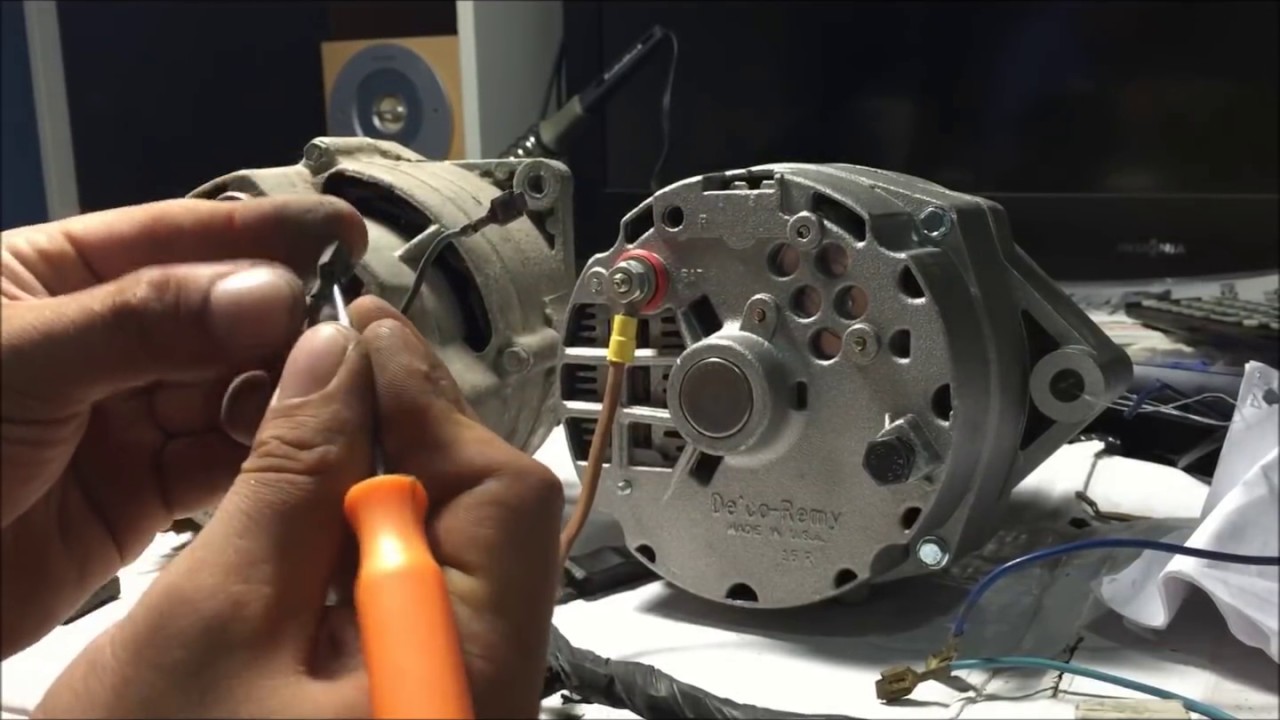
One of the connectors is typically a threaded bolt protruding from the back (the opposite end from the pulley) that a wire with a boot on the connecting end is snapped onto.
Short or open circuits, or high resistances, in the stator windings. Alternators have replaced dynamos as generators on modern cars; Diode faults, caused by heat and vibration or the inclusion of moisture into the circuitry. In this article, the design of the alternator circuit will be explained in detail, with some trouble shooting tips. The diode trio takes current coming from the three stator windings and passes a small amount through three diodes so that only the positive. The alternator has a rotor that spins when the engine cranks. If the alternator should fail, voltage from the diode trio would drop, and once again the lamp would light from the battery voltage. Typical alternator, or related, faults are: Amperage (amp, or ampere) is a measure of electrical current flow. A key to identifying your alternator terminals posted by peter kennedy on 12/13/2018 to alternators this key might be helpful to identify the terminals on your alternators, as you can see the same function can have different designations depending on the make and model of alternator Alternators that have one positive wire connected to the alternator has the ground connected to its case. If the functioning of a traditional car alternator. Occasionally, a linear alternator or a rotating armature with a stationary magnetic field is used.
At this time, with 12 volts on both sides, the lamp is out. This rotor spins past wire coils causing a magnetic field. There is another circuit in the alternator to control the charging system warning lamp that is on the dash. The voltages from a power supply are held within a limit that is consistent with the other electrical components by. • ig is the ignition input that turns on the alternator/regulator assembly.
how to check if alternator is charging - YouTube from i.ytimg.com The first is the alternator output rating, which is the amount of current that a unit is capable of producing at a specific rotational speed. The alternator senses the voltage and regulates. The other end of this wire should be connected to the +12v terminal on the backside. Today, i will be sharing some basic info about the terminal connections of an alternator with full explanation about its working of it field (rot. The alternator has a rotor that spins when the engine cranks. The voltages from a power supply are held within a limit that is consistent with the other electrical components by. P0562 (charging system low voltage). A car uses quite a lot of electricity to work the ignition and other electrical equipment.
In the compressed air system, psi (pounds per square inch) is the measure of pressure.
Short or open circuits, or high resistances, in the stator windings. Never make or break any connection while the engine is running. 12 volt alternator installation operation manual introduction thank you for choosing a balmarr high output alternator. • s is used by the regulator to monitor charging voltage at the battery. P0562 (charging system low voltage). Alternators that have one positive wire connected to the alternator has the ground connected to its case. The voltages from a power supply are held within a limit that is consistent with the other electrical components by. General overview of how an alternator works.how an automotive alternator works tutorial autoshop 101. They can produce more current. First, we will discuss how an alternator works. Diode faults, caused by heat and vibration or the inclusion of moisture into the circuitry. Wiring diagram contains several comprehensive illustrations that display the link of assorted items. In principle, any ac electrical generator can be called.
A key to identifying your alternator terminals posted by peter kennedy on 12/13/2018 to alternators this key might be helpful to identify the terminals on your alternators, as you can see the same function can have different designations depending on the make and model of alternator Wiring diagram contains several comprehensive illustrations that display the link of assorted items. These are known as the l, ig, s, b and f terminals. It consists of guidelines and diagrams for various types of wiring strategies and other products like lights, home windows, etc. Voltage (volt) is a measure of electrical pressure.
Chevy External Voltage Regulator Wiring Diagram - Wiring ... from i.ytimg.com Alternators have replaced dynamos as generators on modern cars; Poor battery states of health or charge. • ig is the ignition input that turns on the alternator/regulator assembly. At this time, with 12 volts on both sides, the lamp is out. The other end of this wire should be connected to the +12v terminal on the backside. Half of the plates are connected to each terminal. For reasons of cost and simplicity, most alternators use a rotating magnetic field with a stationary armature. Once the alternator is at full output, voltage from the diode trio, also applied to 1, equals the battery voltage.
The headlights, dashboard lights, radio and interior lights all rely on the alternator to keep the battery charged and the car operating.
Typical alternator, or related, faults are: Alternators have replaced dynamos as generators on modern cars; The following information is presented as a guide when wiring and troubleshooting alternators. • s is used by the regulator to monitor charging voltage at the battery. These are known as the l, ig, s, b and f terminals. Never make or break any connection while the engine is running. Poor battery states of health or charge. For instance, a 100a alternator has a rated output of 100a, which means that it is capable of providing 100a when the. In the compressed air system cubic feet of air is the similar measure of quantity. The working principle of an alternator is very simple. The other end of this wire should be connected to the +12v terminal on the backside. Diode faults, caused by heat and vibration or the inclusion of moisture into the circuitry. A basic alternator is made up of a series of alternating finger pole pieces placed around coil wires called field windings that wrap around an iron core on the rotor shaft.